X5000
Introduction
This page provides information repository about the X5000 computer from A-EON Technology Ltd.
Motherboard Variants
The X5000's CPU features a 64-bit PowerPC e5500 Architecture-based microprocessor core from Freescale Semiconductor.
It has two main variants of motherboard:
- X5000/020 with P5020 Dual Core CPU running at a clockspeed of 2Ghz
- X5000/040 with P5040 Rev C Quad Core CPU running at a clockspeed of 2.2Ghz
Motherboard Connectors
Back panel from left to right:
- serial RS-232
- ethernet RJ-45 10/100/1000 mbps
- 2x USB 2.0 type A female
- 2x USB 2.0 type A female
- 2x USB 2.0 type A female
On board:
- 2x USB 2.0 header
- SATA 0
- SATA 1
- DIMM 0 DDR3
- DIMM 1 DDR3
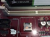
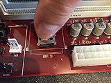
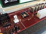
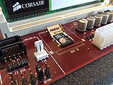
- micro SD card ROM
- CR2032 battery for real time clock
- PCI-E x16 slot
- PCI-E x4
- PCI-E x1 / Xorro
- PCI-E x1
- PCI-E x1
- PCI 5v 32-bit 33Mhz
- PCI 5v 32-bit 33Mhz
- Haze Xorro Header
Memory Configuration
- X5000/20 requires a minimum specification of DDR3 1333Mhz standard 1.5v DIMM
- X5000/40 requires a minimum specification of DDR3 1600Mhz standard 1.5v DIMM
It is recommended to use DIMMs in matched pairs. The total physical maximum size of memory that the memory controllers can address is 64GB, however the practical memory size limit will depend on software.
| size | speed | manufacturer | part number | X5000/20 | X5000/40 |
|---|---|---|---|---|---|
| 2GB | 1333Mhz | Corsair | VS2GB1333D3 | Yes | No |
| 4GB | 1600Mhz | Kingston | HX316C10F/A | Yes | Yes |
| 4GB | 1600Mhz | Kingston | HX316C10FW/4 | Yes | Yes |
Hardware Revision History
- Version 1.0: micro-ATX form factor produced in early 2012
- Version 2.0: full ATX form factor produced in early 2013
- Version 2.1: full ATX form factor supplied to beta testers in 2014-15
- Version 2.2: full ATX form factor consumer release produced in 2015
The revision number is written on the X5000's Cyrus motherboard above the DIMM memory slot.
Firmware
The X5000 uses a 4GB micro SD card as it's ROM. This contains the system's firmware and is removable for reflashing. The card does not have a filesystem so only RAW data maybe copied to it.
The system uses a modified Uboot firmware which includes a graphical front end that is displayed if the user presses the Escape key on system startup.
Click here for a guide to writing your firmware from OS4 and Uboot.
Restoring the MAC addresses after flashing firmware
To reset your ethernet MAC addresses correctly after a firmware update, perform the following steps:
1. Whilst the animated ball title screen is being played, press the ESC key to display the Early StartUp Control menu
2. Select the Command Line option or press the m shortcut key
3. At the X5000> prompt enter the following (pressing enter after each line):
setenv ethaddr
setenv eth1addr
setenv eth2addr
saveenv
4. Once this is saved, reset the system. This will now force the motherboard to retrieve the correct MAC addresses and record them.
All future firmware updates have empty MAC addresses so this process can be performed to retrieve the correct values.
Additional UBoot Options
The new Uboot includes the options to reduce or eliminate the rotating ball animation. Additionally it also includes a special default time-out option.
Three new environment firmware variables are included:
amigabootmenu_animate default 1: Set to 0 to disable the boot animation. Set to 1 to enable the animation.
amigabootmenu_animcycles default 10: Specifies how many times the animation should be played before the default boot selection is booted. Only has an effect if amigabootmenu_animate is set to 1.
amigabootmenu_timeout default 0: If set to a non-zero value, it specifies how many seconds should elapse before the deafult boot selection is booted. This mechanism overrides amigabootmenu_animcycles, so if both are set, this one takes preference.
The result is the boot-up time can be greatly reduced. e.g. ~30+ seconds from power-up to Workbench if amigabootmenu_animcycles=1 and amigaboot_quiet=y
Motherboard LED Status
| label | colour | description |
|---|---|---|
| LED1 | green | standby power indicator |
| LED3 | red | CPU Platform voltage power good (CPLD controlled) |
| LED4 | red | CPU Core A voltage power good (CPLD controlled) |
| LED13 | red | CPU Core B voltage power good (CPLD controlled) |
| LED14 | red | DDR 3 voltages power good (CPLD controlled) |
| LED15 | red | IO voltages power good (CPLD controlled) |
| LED5 | red | PORESET state indicator (CPLD controlled) |
| LED6 | red | HRESET state indicator(CPLD controlled) |
| LED7 | red | ASEELP state indicator (CPLD controlled) |
| LED16 | red | STANDBY state indicator (CPLD controlled) |
| LED8 | red | MCU temperature warning LED |
| LED9 | red | MCU error LED |
Technical Reference Manual
The official Technical Reference Manual can be downloaded from the AmiSphere server (an AmiSphere account is required)
Technical Reference Manual v1.1.1 PDF
Note: this copyrighted document should not be distributed on any other website
Trivia
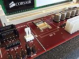
There is a long running tradition, started originally by Commodore engineers, on having The B-52s song titles on Amiga compatible hardware. The X5000 motherboard is no exception to this tradition as it features Breezin' on the silkscreen.
The motherboard is codenamed Cyrus in homage to the character Cyrus Smith (named Cyrus Harding in some English translations) who is one of the protagonists of Jules Verne's novel The Mysterious Island.

